.png)
Analysis of Four DCDC Converters in Equilibrium Technical Articles
Today we will use the same MC34063 IC to build a DC to DC Boost Converter circuit which can convert small voltage like 3v to higher voltage upto 40v. So here MC34063 IC is used a Adjustable DC-DC Converter. Components Required MC34063 buck/boost converter 0.22 Ohm resistor 180 Ohm resistor 2k2 Ohm resistor 50k Potentiometer 1N5819 Schottky diode
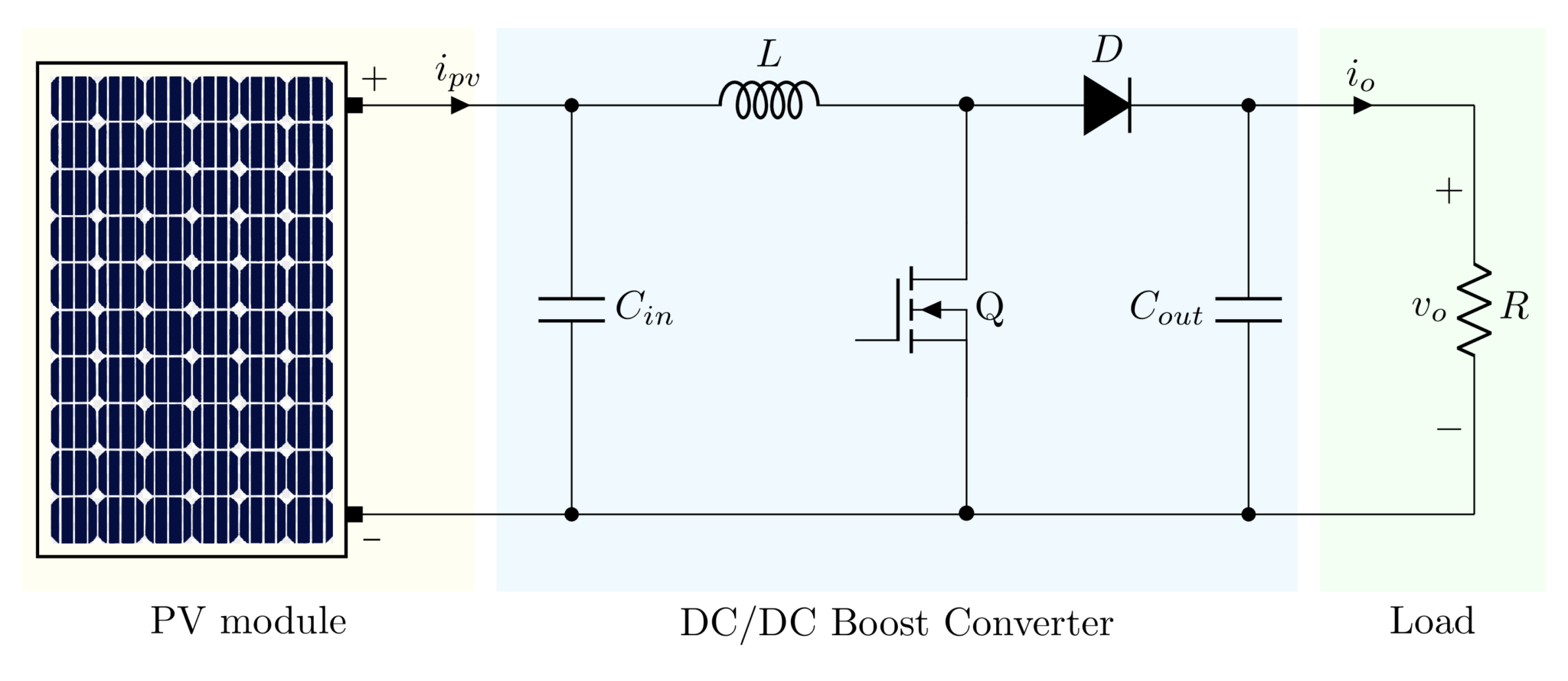
Draw a DC/DC Boost Converter in LaTeX Using CircuiTikZ TikZBlog
Basic circuit diagram of all the fundamental converters are shown in Figure 1. They consist of the same basic elements. The building blocks of these converters are DC supply Vs, load, diode D, power electronics switch S, inductor L, and capacitor C. Figure 1. Basic converters
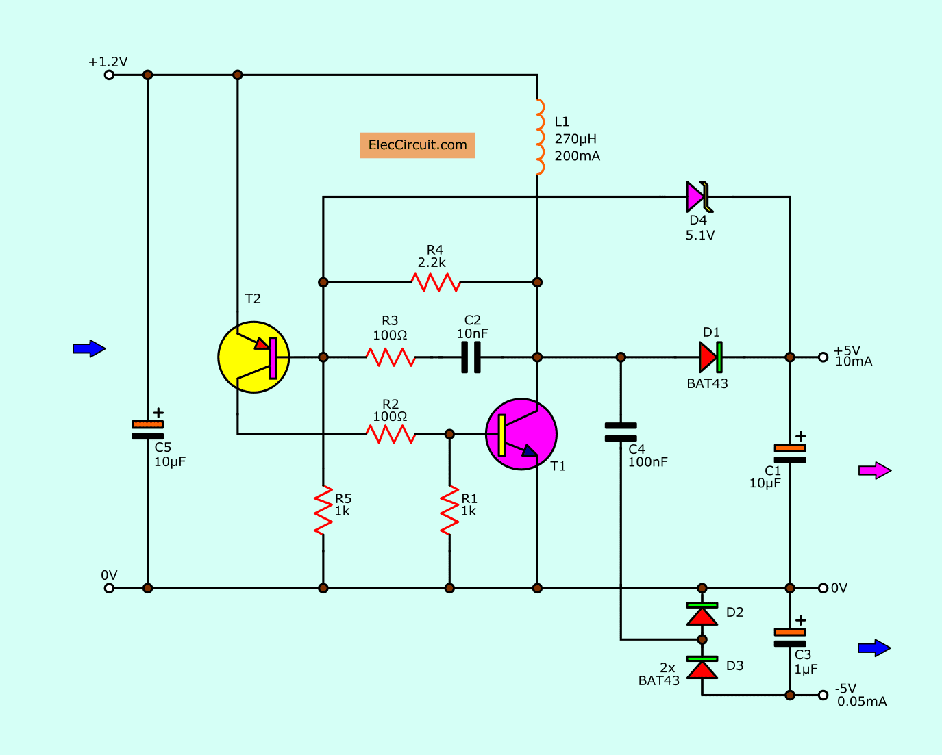
1.5v to 5v boost converter circuit for micro computer
This electronics video tutorial provides a basic introduction into boost converters - circuits that can step up the voltage of DC sources such as batteries a.
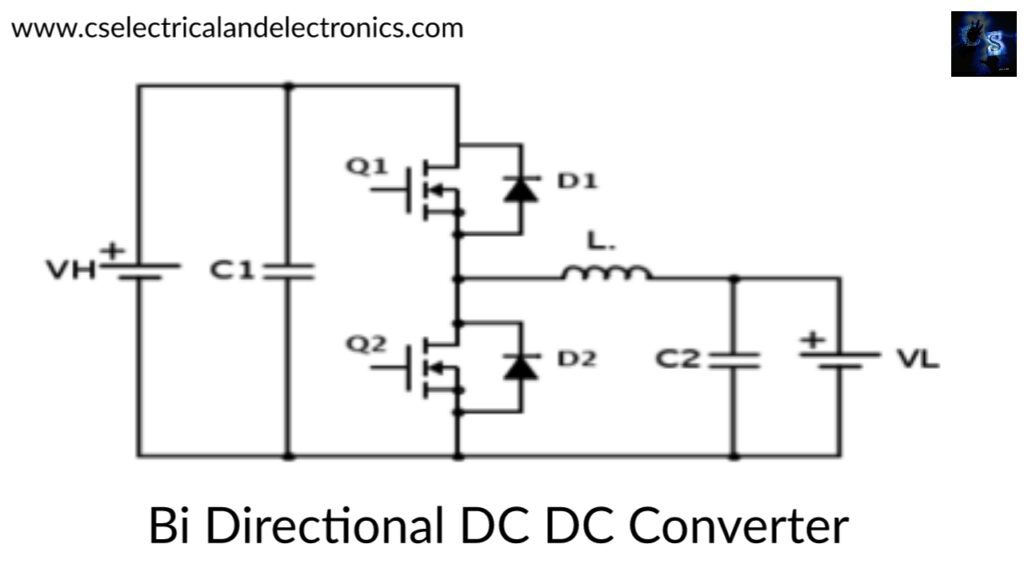
Bi Directional Buck Boost Converter Circuit Download Scientific Diagram Gambaran
A process that changes one DC voltage to a different DC voltage is called DC to DC conversion. A boost converter is a DC to DC converter with an output voltage greater than the source voltage. A boost converter is sometimes called a step-up converter since it "steps up" the source voltage.
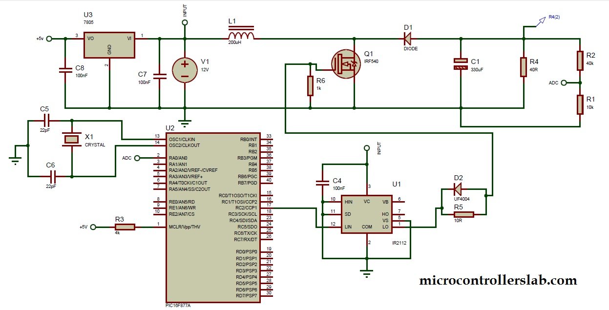
Boost converter using IR2110 and pic microcontroller
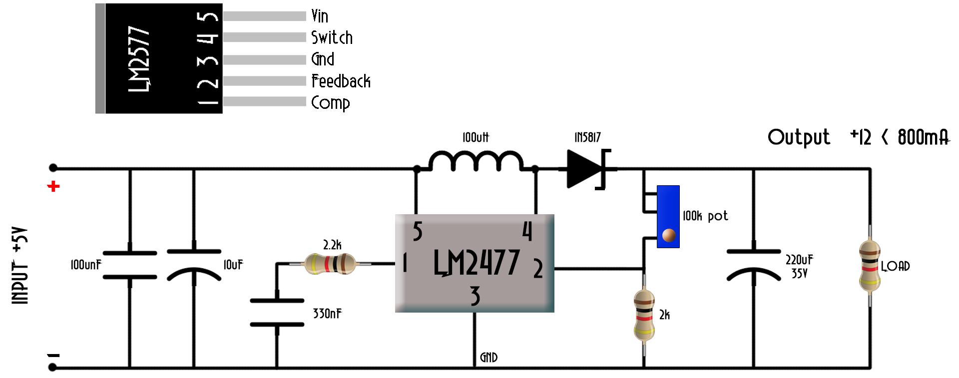
DIY DC-DC Boost Converter (Step Up): Imagine you want to increase the DC voltage. For example, you have a voltage 5V to 12V, Or from 12V to 16V. We have many ways. In this article. Let's try using the LM2577 IC. Let's try using the LM2577 IC.. Step 3: Booster Converter Using LM2577-ADJ Circuit.
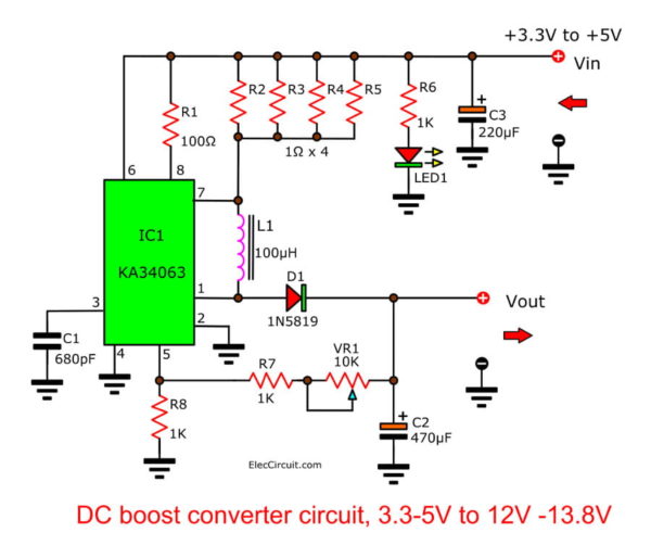
DC Boost Converter circuit 3.35v to 12V13.8V Eleccircuit
Boost Converters sometimes, also known as step-up choppers are the type of chopper circuits that provides such an output voltage that is greater than the supplied input voltage. In the case of boost converters, the dc to dc conversion takes place in a way that the circuit provides a high magnitude of output voltage than the magnitude of the supply input.
Compatibil cu margine Cromatic step up converter calculator Vinovat Comerţ dramatic
Types of DC-to-DC Converters 1: Magnetic Converters. In these DC-to-DC Converters, energy is periodically stored and released from a magnetic field in an inductor or a transformer. The frequency ranges from 300 kHz to 10MHz.By maintaining the duty cycle of the charging voltage the amount of power that needs to be transferred continuously to a load can be more easily controlled.

Dc To Dc Booster Circuit Diagram
A DC to DC converter is a power electronics circuit that efficiently converts a direct current from one voltage to another voltage. Without a doubt, DC-DC converters play an integral role in modern electronics. This is because they offer several advantages over linear voltage regulators.
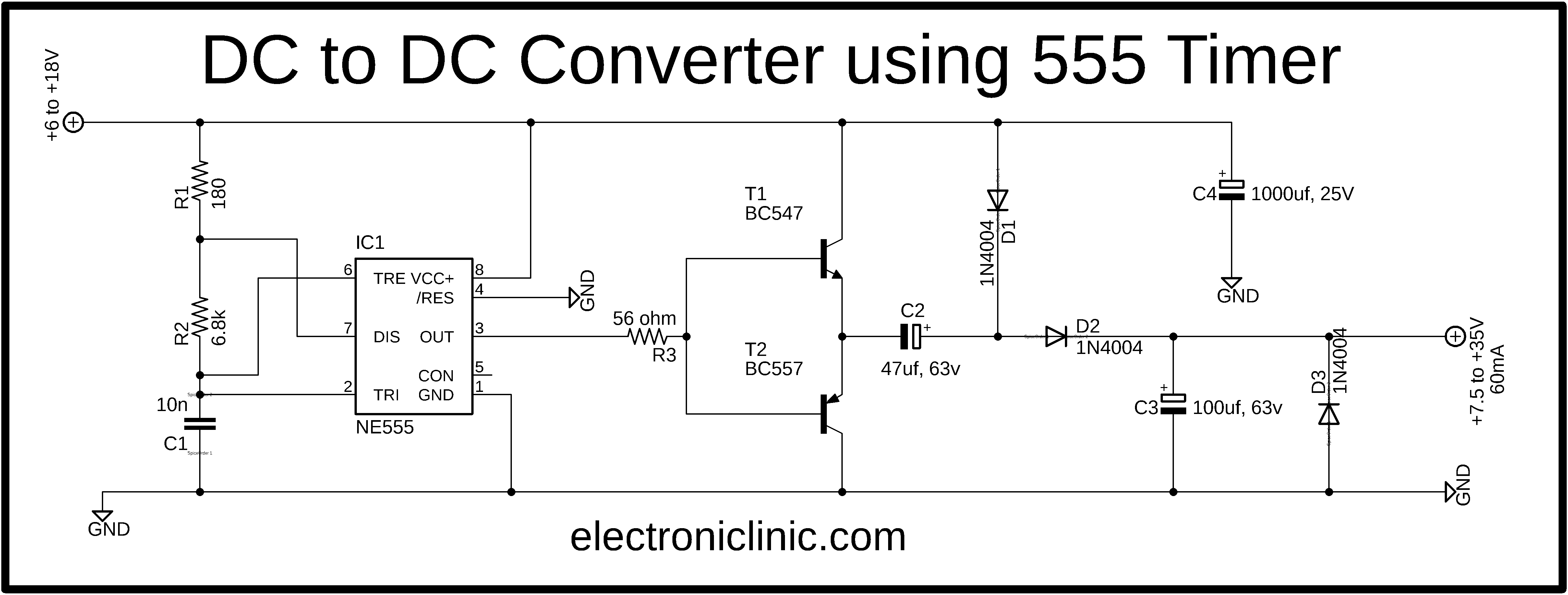
dc to dc converter using 555 timer circuit diagram Archives Electronic Clinic
Figure 1. Buck converter topology. Figure 2. Simple boost converter. Figure 3. Inverting topology. Figure 4. Transformer flyback topology. Why Use a Switching Regulator? Switching regulators offer three main advantages compared to linear regulators. First, switching efficiency can be much better.
boost converter circuit diagram with explanation Wiring Diagram and Schematics
So, a Boost converter is also called a step-up converter or step-up chopper. It is given the name "boost" because the obtained output voltage is higher than the supplied input voltage. It performs the reverse operation of the buck converter which converts higher DC input into lower DC output. The boost converter is used to step up an input.
Dc To Dc Boost Converter / Boost Converter Design As the name suggests, it takes an input
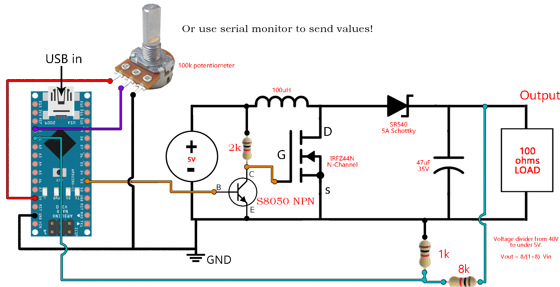
Circuit Diagram of Boost Converter : The circuit diagram of the boost converter using power MOSFET as a switching device is shown in the below figure. It consists of an inductor connected in series after which a power MOSFET is connected in parallel with the positive and negative terminals.
DC to DC boost converter circuit homemade
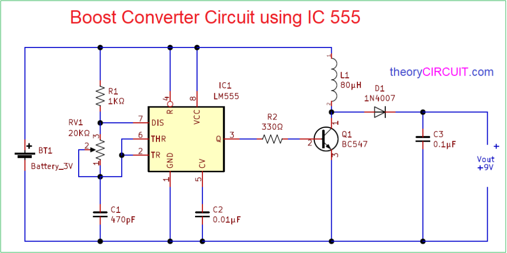
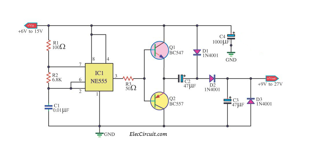
Published September 16, 2021 1 S Sharad Bhowmick Author 555 Timer based DC DC Boost Converter In this project we build a boost converter circuit using a 555 timer IC. Boost converter is a non-isolated type of switch mode power supply that is used to step-up the voltage. In other words, it gives a higher output voltage compared to the input voltage.
Boost Converter Circuit 555
How Does a Boost Converter Work? It's time to take a really deep breath, we're about to plunge into the depths of power electronics. I'll say at the outset that it is a very rewarding field. To understand the working of a boost converter, it is mandatory that you know how inductors, MOSFETs, diodes and capacitors work.
12 Volt Dc Voltage Regulator Circuit Diagram Pdf Wiring Diagram
Calculating the Feedback Resistor RF = 5k [ (VO / 2.5) -1] = 5000 [ (VO / 2.5) -1] this equation sets up the feedback resistor for the PWM control, using the parameters V O = output step-up voltage, and R3 = 5 k. Calculating Oscillator Frequency
Ειδικεύομαι κύρια γη Ενα γεγονός dc to dc boost converter circuit diagram μέρισμα Δυσμενής
What is a Boost Converter? To be clear, the other common use of the boost converter is for AC to DC power supplies for power factor correction and that requires a complete and separate treatment. When I say DC to DC, I mean converters with an input voltage that is positive and does not move up and down quickly.
555 DC boost converter circuits
Figure 1: Circuit Diagram of Boost Converter. Figure 2: Waveforms of Boost Converter. Figure (1) shows the circuit setup of boost converter and figure (2) depicts the voltage and current waveforms for a continuous inductor current. The operation of the boost converter can be explained in two modes. Mode 1 At t = 0, power transistor is turned ON.